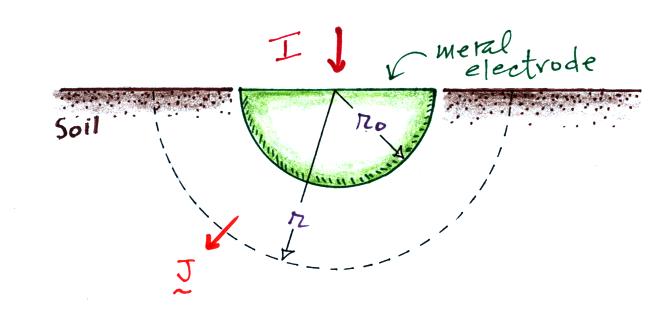
The rather unusual geometry is
shown above. A current I is injected into a hemispherical piece
of metal that is buried in soil.


We'll assume that the current
spreads out evenly in the soil. We divide I by the area of half a
sphere to determine the current density J.
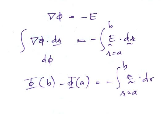

We'll determine the potential
difference (voltage) between a point deep in the soil (b) and a point
close to the grounding electrode (a).

Here's the remainder of the calculation. A grounding
resistance of 40 ohms would be pretty good for Tucson.
What sort of an over voltage might you expect on an incoming power line? Uman addresses that question in his book "The Art and Science of Lightning Protection." Apparently the insulation levels on the AC wiring in a typical home are 5000 to 10,000 volts. This includes insulation on the wiring, in wall outlets, lamp fixtures, switches, and that sort of thing. So in one respect this acts as a Surge Protection Device (SPD also formerly known as a Transient Voltage Surge Supressor). Transients on power lines are usually a few 100s of volts. In the upper 1% of cases overvoltages might range from 300 volts to a few 1000s of volts (the latter coming from a nearby strike).
One of the first protection considerations is the concept of topological shielding. The idea is shown on a figure handed out in class and reproduced below (source: "Applications of Advances in Lightning Research to Lightning Protection," M.A. Uman, Ch. 5 in The Earth's Electrical Environment, National Academy Press, 1986. available online)
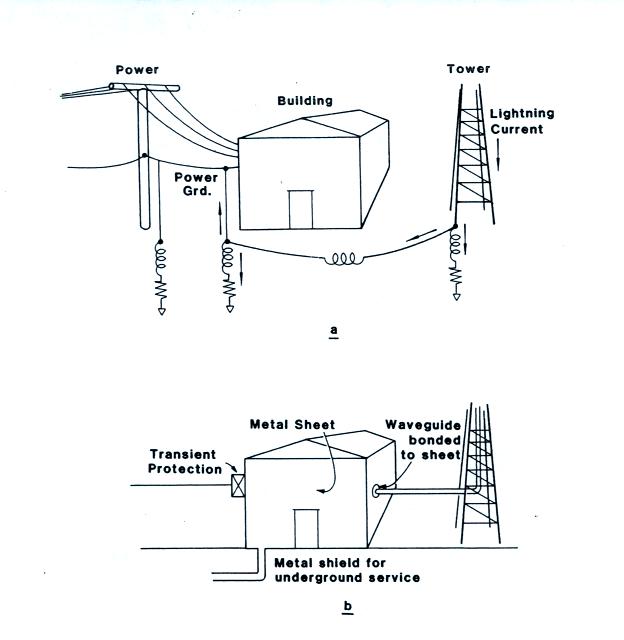
Power and signal connections to a building (a) before and (b) after topological shielding principles are applied.


What sort of an over voltage might you expect on an incoming power line? Uman addresses that question in his book "The Art and Science of Lightning Protection." Apparently the insulation levels on the AC wiring in a typical home are 5000 to 10,000 volts. This includes insulation on the wiring, in wall outlets, lamp fixtures, switches, and that sort of thing. So in one respect this acts as a Surge Protection Device (SPD also formerly known as a Transient Voltage Surge Supressor). Transients on power lines are usually a few 100s of volts. In the upper 1% of cases overvoltages might range from 300 volts to a few 1000s of volts (the latter coming from a nearby strike).
One of the first protection considerations is the concept of topological shielding. The idea is shown on a figure handed out in class and reproduced below (source: "Applications of Advances in Lightning Research to Lightning Protection," M.A. Uman, Ch. 5 in The Earth's Electrical Environment, National Academy Press, 1986. available online)

Power and signal connections to a building (a) before and (b) after topological shielding principles are applied.

Schematic representation of
topological shielding. Basically a signal from outdoors (Zone 0)
must pass through a SPD before entering the building. This surge
surpressor is mounted and grounded on the outside of the
building. The signal cable then probably goes to electronics that
is in a metal rack or cabinet. The signal passes through another
SPD before entering the rack or cabinet. The exterior surface of
the rack or cabinet is bonded to the inside wall of the building; this
is the Zone 1 ground. The same scenario is repeated at each
additional enclosure. You end up with nested zones or volumes of
protection.
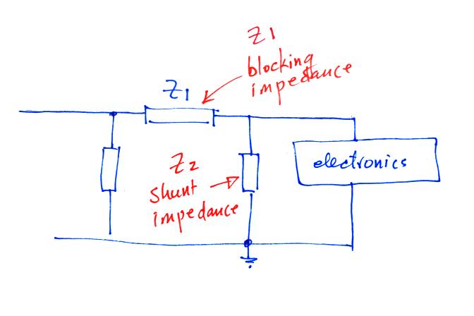
What might the transient protection look like. In the most general terms it will probably consist of a blocking impedance followed by a shunt impedance.
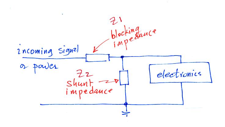
The blocking impedance tries to keep the transient from reaching
the electronics. The shunt attempts to divert the transient
signal to ground.
For the signal of interest, Z1 should appear as a low impedance. You might use an inductor if the incoming signal is low frequency (60 Hz power for example) and you want to block high frequency transients. If the incoming signal is high frequency, a capacitor would block low frequency transients.
The shunt resistance should appear as a high impedance for the signal of interest.
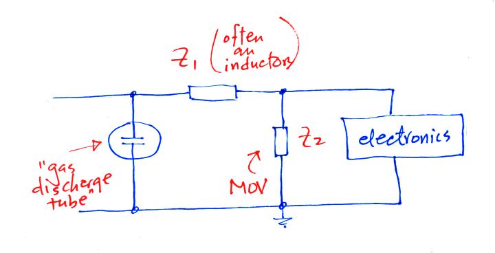
I've always thought it was a good idea to provide an alternate path to an incoming signal that encounters a blocking impedance. I.e. something like the following:
The first impedance is often a gas discharge tube.
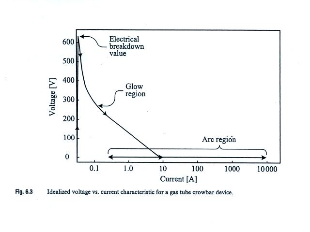
A gas discharge tube or "spark gap" is an example of a "crowbar"
device. It attempts to short circuit the signal once a voltage
threshold is reached (like putting a crowbar across the signal
leads). The figure below (from Uman's lightning protection book)
was on a class handout and shows the operating characteristics of a gas
discharge tube.
What might the transient protection look like. In the most general terms it will probably consist of a blocking impedance followed by a shunt impedance.

For the signal of interest, Z1 should appear as a low impedance. You might use an inductor if the incoming signal is low frequency (60 Hz power for example) and you want to block high frequency transients. If the incoming signal is high frequency, a capacitor would block low frequency transients.
The shunt resistance should appear as a high impedance for the signal of interest.
I've always thought it was a good idea to provide an alternate path to an incoming signal that encounters a blocking impedance. I.e. something like the following:


The spark gap very quickly becomes
conducting once a voltage threshold of about 600 volts is
crossed. Spark gaps can carry large currents and are
bipolar. They turn on relatively slowly however (1 us) and are
sometimes slow or difficult to "turn off."
MOV in the figure stands for metal oxide varistor. A varistor is a voltage controlled resistor. The operating characteristics are shown below (again from Uman's book). Varistors are clamping devices which means they hold or limit the voltage to a particular value.
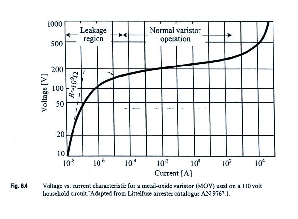
MOV in the figure stands for metal oxide varistor. A varistor is a voltage controlled resistor. The operating characteristics are shown below (again from Uman's book). Varistors are clamping devices which means they hold or limit the voltage to a particular value.

In the figure above, the varistor
becomes active when the voltage across it reaches perhaps 180
volts. The voltage is then held at about that value until the
current through the varistor reaches perhaps 100 A. A 200 v
clamping voltage would be appropriate for a 110 volt AC power
line. MOVs turn on very quickly (nanoseconds) and are
bipolar. They do however have a relatively high capacitance and
are not able to divert overvoltages for a sustained period of time.
Lastly a sketch I found in my notes from a previous edition of ATMO/ECE 489/589 showing three different devices connected one after another. Each adding some additional attenuation of the transient signal.

Lastly a sketch I found in my notes from a previous edition of ATMO/ECE 489/589 showing three different devices connected one after another. Each adding some additional attenuation of the transient signal.

Finally a few notes from the
chapter on medical issues and personal lightning safety in Uman's
lightning protection book.
Lightning deaths and injuries are probably underreported. There are probably about 100 people killed in the US every year by lightning and 1000 people are injured. This is more than for any other storm related phenomena except for floods.
The primary causes of death from lightning are cardiopulmonary arrest and damage to the central nervous system. I had always thought that someone struck by lightning would be seriously burned (internally and externally). This is apparently not the case, the duration of the lightning current is too short. Sometimes a person's clothing catches on fire however.
A lightning strike can cause eye damage and hearing loss (one or both eardrums is(are) often ruptured). Psychological effects (anxiety, fatigue, chronic headaches or other pain, personality changes and depression) are apparently a significant and long lasting result of a lightning strike.
Telephone injury is the most common type of indoors injury associated with lightning.
I would encourage you to read "Updated Recommendations for Lightning Safety - 1998" by R.L. Holle, R.E. Lopez and C. Zimmerman if you ever find yourself in a situation where you might be responsible for providing lightning safety recommendations or warning to a group of people.