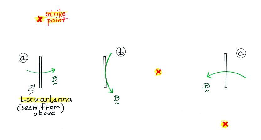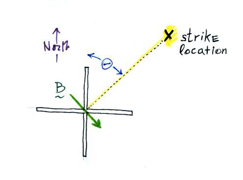
We want to be able to determine theta using measurements from a NS loop
and EW loop antennas. We'll look at the output from the NS loop
first.
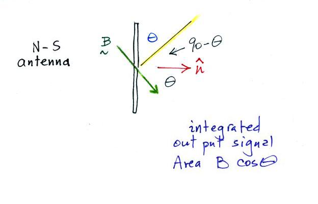
The output signal is proportional
to the cosine of the bearing angle.
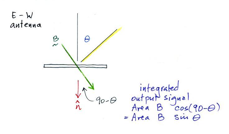
The signal from the EW loop is
proportional to the sine of the bearing angle.
The bearing angle can be determined by taking the inverse tangent
of the ratio of the two loop antenna signals.
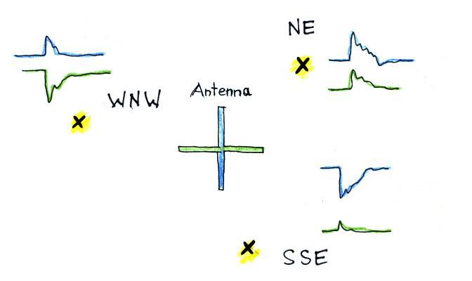
Examples of NS signals and EW signals that you would expect to see
for strikes to the NE, SSE, and WNW of the orthogonal loop
antenna. And something that I didn't mention in class: the square
root of the sum of the squares of the two signals gives you the B field
amplitude.

Once the distance to the discharge
is determined, the B field ampltitude (assumed to be purely radiation
field) can be used in the transmission line model to estimate the peak
current in the stroke. Of course you could also use the E field
to estimate peak current.
A class handout showing the orthogonal loop antenna used in the
original lightning direction finding system was distributed in
class. The figures can be found in "Lightning
Direction-Finding
Systems
for
Forest Fire Detection," E.P. Krider, R.C.
Noggle, A.E. Pifer, and D.L. Vance, Bull. Am. Meteorol. Soc., 61,
980-986, 1980. (link to a PDF file). The
original antenna was a PVC pipe structure perhaps 8 feet tall. A
picture of the next generation antenna, maybe only 2 or 3 feet tall is
also shown in the publication. It is worth mentioning that the
original DF systems were being used for forest fire prevention in
Alaska.
The publication cited above also contains examples of typical lightning
return stroke radiation field waveforms (the E and B radiation field
waveforms are essentially identical). An example of a large
amplitude signal from a cloud discharge was also shown. Typical
cloud-to-ground and cloud discharge waveshapes are sketched below
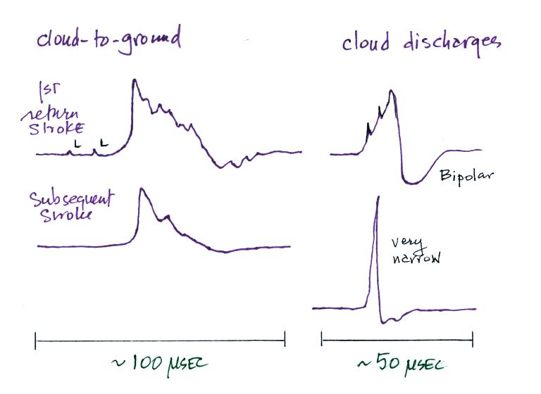
Once a lightning signal is detected
by a magnetic direction finder sensor, the waveform must pass a series
of waveshape tests. The main objective being to discriminate
between return stroke waveforms and waveforms from large amplitude
cloud discharges. We have implicity been assuming in our
discussion that the lightning channel is vertically oriented.
This is a pretty reasonable assumption for cloud-to-ground discharges,
especially when the return stroke is close to the ground. Channel
tilt will add signficant errors to the estimate of bearing angle.
Cloud discharge channels can be tilted and are often essentially
horizontal.
If the waveform passes the waveshape tests, the peak ampltitudes
of the NS and the EW signals are determined. At the time of peak
signal, the return stroke is probably within about 100 m of the
ground. Estimating the bearing angle at this time is advantageous
because you eliminate the effects of channel branches, the channel is
often fairly straight and vertical near the ground, and you're
determining a direction to where the return stroke struck the ground.
Once bearing angle estimates are made at multiple DF sensor
locations, you can then triangulate to locate the lightning strike
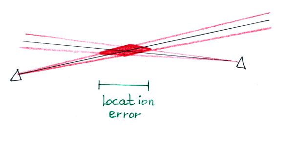
point. Errors in the bearing angle estimate of course
lead to uncertainty in the lightning strike location.
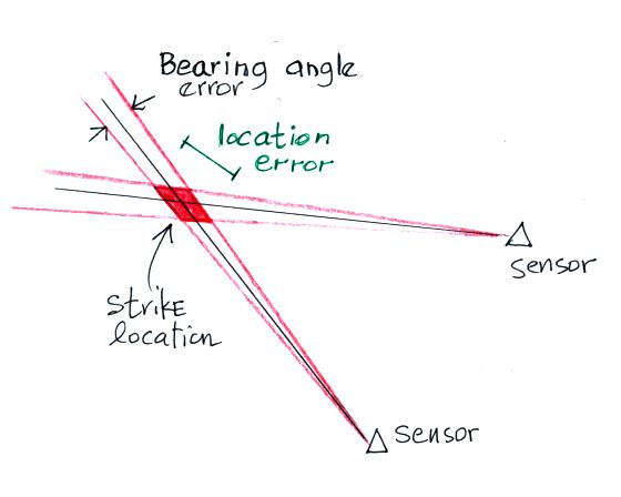
Here we see the location determined
using bearing angles from only 2 sensors (the minimum number
required). In the current NLDN network return strokes with a
current of 25 kA would be detected by 6-8 sensors. There are
sophisticated methods for determining the optimal location with
redundant data like that.
Large location errors can be present when a lightning strike is on
or near a baseline between two sensors.
Of course with redundant data like you have in the NLDN other sensors
would be of the baseline and would provide more accurate location
information.
It became evident in early incarnations of the NLDN that sufficient
location accuracy would not be possible using magnetic direction
finding alone unless sensors were on the order of 100 km apart.
Operation of a network with that kind of density would be too
expensive. In the current network sensors are 300 to 350 km apart
(there are just over 100 sensors I believe in the current network).
