
The house has a length of 20 m, a
width of 12 meters and the top of the pitched roof is about 5 m
high. To determine the effective area we must extend the actual
dimensions of the house by 2 times the height (2 x h) on all four sides
of the house.

An interesting survey of the costs of various
types of lightning damage was on a handout distributed in class.
This came from the first 3 or 4 pages in Chapter 2 of Uman's The Art
and Science of Lightning Protection. Here are a few of the
figures on the handout:
The 1977 power blackout in
Estimates of the costs of lightning damage to
insurance companies range from 1/3 to $1
billion. In total about 5% of insurance claims involve lightning
(50%
in
30,000 house fires caused every year by lightning. About half of the 20,000 wildfires every year are caused by lightning. The cost of fighting wildfires was about $1.5 billion in 2006 (a record year).
Lightning damage to commercial airlines costs
~$2 billion per year. Damage to military aircraft is comparable.
Lightning causes damage to perhaps 100,000 computers/year.


Lightning protection for a house or
building usually consists of 3 components:
For structures less than 50 feet tall
a lightning rod provides a 45o
or 60o cone of
protection. The 45o
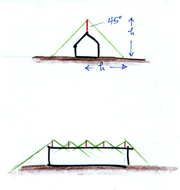
A larger structure can be protected with
multiple rods with overlapping zones of protection.
A different approach is used for larger structures. We need
to recall that the striking distance, d, is the distance between
the leader tip and the moment upper connecting discharges are initiated
at the ground. The leader can potentially strike anything withing
a d of the leader tip.
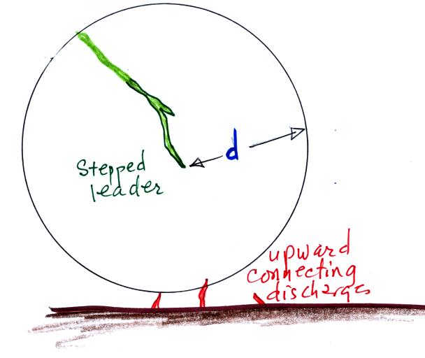
In the rolling sphere method, you imagine rolling a sphere of radius d
(d is the striking distance) over the building being evaluated for
lightning vulnerability. Parts
of the building touched by the sphere are at risk. Portions that
aren't touched are safe.

The height of the building at
left is less than or equal to d. The sides of the building aren't
touched by the sphere, the top is. Lightning protection would
need to be installed on the roof. The building at right is quite
a bit higher than d. Much of the sides as well as the roof can be
struck by lightning. Protection would need to be installed on the
top sides of the building and the roof. Fragments of building
materials knocked off the sides of buildings by lightning are
apparently a serious hazard to people on the street below.
The designers could make metal window shades and window frames part of
the lightning protection system by connecting them to the down
conductor.

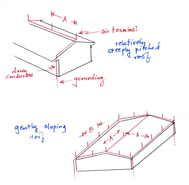
Note the spacing of the air
terminals must be such that the rolling sphere doesn't touch the roof
in between adjacent lightning rods.
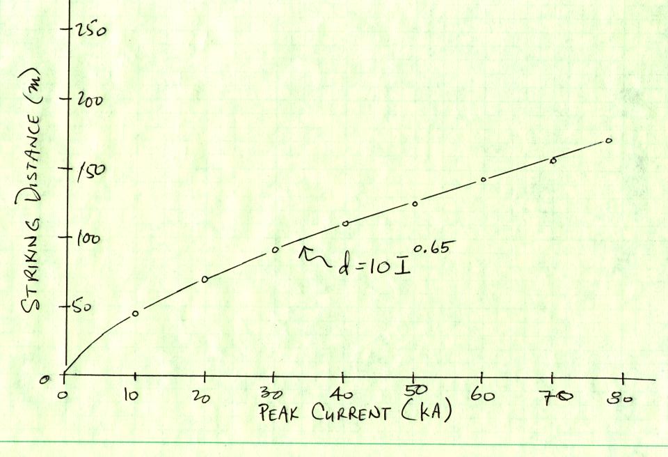
What value of d should be used? Researchers have tried to relate
the striking distance to the amplitude
of the peak return stroke that follows. Generally an expression
of the form
is used. A class handout
showed curves drawn using the most commonly assumed values for A and
b. I've one of the curves on that graph below
| protection level |
d |
minimum peak I |
% rs>Imin |
| I |
20 m |
3 kA |
99% |
| II |
30 |
5 |
97 |
| III |
45 |
10 |
91 |
| IV |
60 |
16 |
84 |
Protection of a
roof
A roof can be protected by multiple lightning
rods. An old question whether pointed rods or blunt rods
work
best. Some recent research (two articles by Moore et al, 2000 in
the class articles folder) suggest that the blunt rods might be more
effective. The NFPA allows either type to be used. Rods
should be at least 10 inches tall.
So called "unconventional" rods that use radioactivity or high voltage
to try to initiate an "earlier" upward connecting discharge are
generally not thought to be any more effective than conventional
"Franklin" rods.
A wire mesh covering
the roof of a building or vulnerable installation
on the ground can be used instead of lightning rods. A wire mesh
covered the administration trailer at the rocket triggered lightning
site in Florida for example.
The following table gives recommendations for the spacing of the wires
in a wire mesh (based on Table 4.2 in Uman's "The Art and Science of
Lightning Protection")
| protection level |
d |
mesh spacing |
| I |
20 m |
5 m x 5 m |
| II |
30 |
10 x 10 |
| III |
45 |
15 x 15 |
| IV |
60 |
20 x 20 |
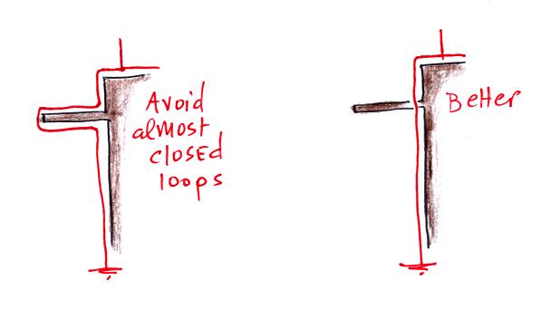
Air terminals should be connected to as many
down conductors as possible. Lightning rods on a house should be
connected to at least two down conductors (at opposite corners of the
house for example).
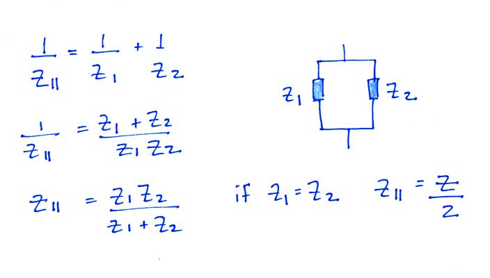
There are several reasons for this:
(i) reduce impedance (connecting inductors or
resistors in parallel reduces the combined impedance)
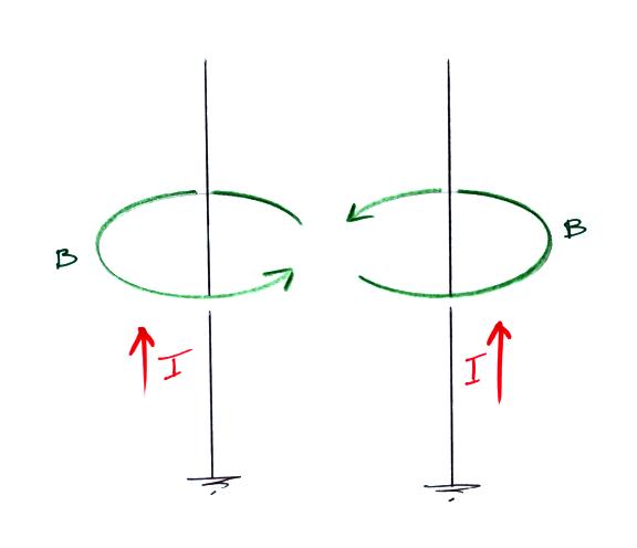
(ii) reduce B fields inside the structure
(the B fields from two down conductors positioned on opposite sides of
a building will point in opposite directions in the interior of the
building)
The recommended minimum crossectional area is about 50 mm2 for copper (that correcponds to a radius of 4 mm, a diameter of 8 mm or roughly 1/3 inch)

3 x 10⁶ V/m is need to breakdown air at sea level
500 kV/m is the average field needed for propagation of negative
polarity leaders
300 kV/m is the average field needed for positive leader propagation.
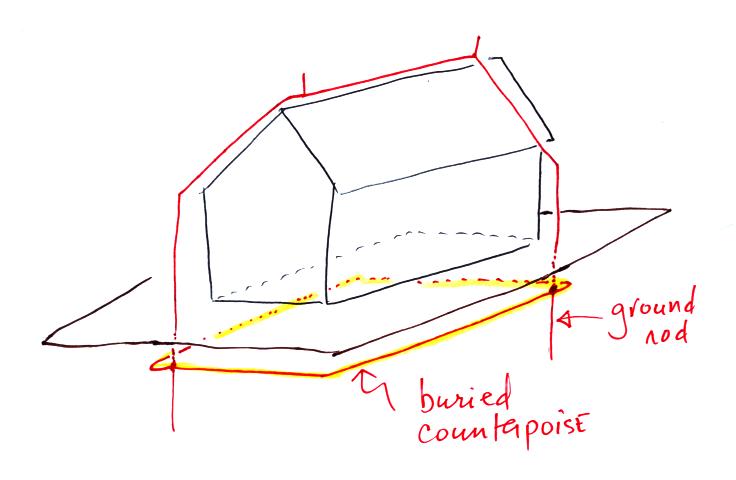
A couple of sections of copper clad grounding rods were shown in
class. Grounding rods should be at least 8 feet long and the
bottom end should be at least 10 feet deep.
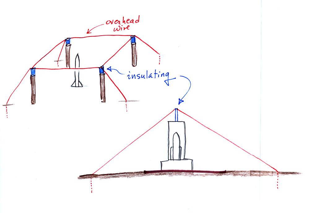
Grounding can be improved by connecting grounding rods to a
counterpoise, a loop of grounding wire that encircles the
structure. This reduces potential differences inside the loop.
A handout had a table of resistivities of various materials (Table
5.1 in Uman's "The Art and Science of Lightning Protection").
material
resistiviy in ohm-meters
ocean water
0.1 - 0.5
ground, well & spring
water
10 - 150
lake & river water
100 - 400
rain water
800 - 1300
commercial distilled water
1000 - 4000
chemically clean water
250000
clay
25 - 70
sandy clay
40 - 300
peat, marsh &
cultivated soil
50 - 250
sand
1000 -3000
moraine
1000 - 10000
ose (calcereous remains)
3000 - 30000
| rod length |
resisitivity 100 ohm-meter |
resistivity 1000 ohm-meter |
| 3 m |
35 ohms |
350 ohms |
| 6 |
22 |
220 |
| 9 |
15 |
150 |
| wire length |
resisitivity 100 ohm-meter |
resistivity 1000 ohm-meter |
| 50 m |
4.0 ohms |
40 ohms |
| 100 |
2.6 |
26 |
| 200 |
1.4 |
14 |